MEASURING
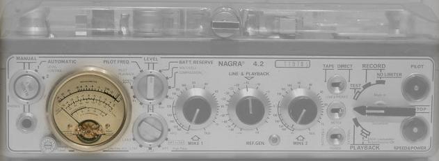
BATTERY RESERVE
When the Meter Switch is put into the "Batt. Reserve" position the meter will indicate the difference
between the power voltage available and the power, which the Nagra needs. Often the two voltages
will fluctuate. The device will take into consideration the lowest instantaneous voltage and
memorize this. This detail is important, for the average voltage of a power supply can be sufficient
but momentary drops in the voltage can happen and drop lower than the required minimum.
New batteries will give about 18 V whereas the Nagra can be powered by up to 30 V. This explains
why, with new batteries, the needle of the meter will only indicate about 40% full scale, when it is
switched to "Batt. Reserve".
VOLT / CELL
The meter switch in this position works as a simple voltmeter. The centre scale is graduated from 0
to 1.6 V, it indicates 1/12 of the total voltage or the average voltage of 1 cell.
The position Volt/Cell is essentially designed to monitor the voltage of some accumulators, which
would be damaged if they were allowed to discharge below a certain value. This value is 1 V /Cell
for certain manganese dioxide alkaline accumulators.
It is also possible to monitor the external power supply voltage. If when in the position "Batt.
Reserve" position the indication is that the Nagra is not receiving sufficient voltage, but the Volt/Cell
indicates that the power supply voltage is correct, this means that the Nagra requires an abnormally
high voltage. Under these conditions the motor and motor collector should be examined.
3.2 TAPE SPEED AND STANDARD SELECTION
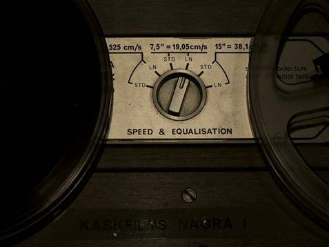
The NAGRA 4.2 is capable of running at three different speeds, which can be selected by changing the position of "SPEED AND EQUALIZATION" selector (20) on the top deck of the recorder between the two spools.
The speeds available are :
3¾ ips (9.525 cm/s)
7½ ips (19.05 cm/s)
15 ips (38.10 cm/s)
Each position of this selector automatically selects the correct equalization of the machine according to the chosen speed. There are two different positions available for each speed and they are marked "I" and "II" which represent Standard and Low noise respectively. For adjustments of equalization and checking of tape speed refer to the 4.2 SERVICE MANUAL.
NOTE: The NAGRA 4.2 is only equipped with one recording bias oscillator and it is therefore only possible to bias the recorder for one specific tape type at any one time. However, it is possible to optimize the equalization in the second position (LN) for a different tape.
LIMITER
The Nagra 4.2 is equipped with a safety limiter, which instantaneously reduces the gain of the recording amplifier when the signal exceeds the maximum level providing that the RECORD with limiter position of the Main Function Selector has been selected. This limiting evidently causes distortion, but it is less objectionable than that caused by saturation of the tape. Normally, the limiter will only be brought into action when accidents occur. It is possible that, in the middle of a dialogue,
for example, a short but high power sounds exceeding the maximum level can occur. Under these conditions it is preferable to saturate rather than to limit because the saturation will be practically unnoticeable due to the short duration of the sound. On the other hand, the limiter requires a certain recovery time before the normal sensitivity of the chain is re-established. This sensitivity variation can affect the ambient sound and can be a greater nuisance than saturation by a brief sound.
6.0 BASIC THEORY
CONTROL OF THE INPUT SENSITIVITY (MODULATION),
RATIO, DECIBELS
The dynamic range is the ratio between the loudest and softest sound levels. The dynamic range is
large for a symphony orchestra compared to that of an announcer reading a news bulletin.
The signal-to-noise ratio is related to the dynamic range. It is important that the softest sound level
to be recorded is still considerably stronger than the noise. Thus, sound with a large dynamic range
requires a high signal-to-noise ratio. However, this ratio can be practically equal to the dynamic
range in the case where the noise level is close to the threshold of audibility. The subjective
perception of the sound level follows a law, which is approximately logarithmic. It is for this reason
that it is customary to measure sound level as a logarithmic unit. This is the decibel (dB). Each time
the sound power is multiplied by 10, the number of decibels, which that represents is increased by
10. Thus an increase of 100 times equals 20 dB, a 1000 times equals 30 dB etc. It should be
remembered that the power is proportional to the square of the amplitude. The voltage, which a
microphone gives, is proportional to the amplitude. In other words if the voltage increases 10 times,
the power increases 100 times and corresponds to 20 dB.
The decibel is a measure of power ratio and not an absolute value. In taking as a reference, a
sound corresponding to a variation of pressure of 2? 10-4 μbar (value considered as the threshold of
audibility at 1 kHz) a scale in absolute value will be obtained. A sound of 90 dB will therefore mean
90 dB above 2? 10-4 μbar. The frequency response of the human ear varies with frequency. In order
to compensate for this, the sound level should be measured with filters simulating the variations of
sensitivity of the ear. Thus the decibels become the phon referred to 2? 10-4 μbar. The
potentiometer scales of the Nagra 4.2 are graduated in decibels referred to 2? 10-4 μbar. At 1 kHz,
these decibels are the same as phons but as the Nagra does not have psophometric filters, it
cannot be considered as a phon meter. With a potentiometer control placed on X dB, a sound of X
dB, captured by a normal microphone (0.2 mV/μbar into 200 ? ) and attacking a normal sensitivity
preamplifier, produces a recording at nominal level. The modulometer will indicate 0 dB.
COMPRESSION OF THE DYNAMIC RANGE
The ideal installation for recording and reproduction should restitute exactly the sound levels, which
have been recorded.
The listener should hear exactly what the microphone heard. The human ear has a dynamic range
of more than 120 dB. The Nagra 4.2 has a signal-to-noise ratio, which is exceptionally high.
However, this ratio can only just reach 70 dB. An amateur tape recorder should, according to the
DIN standard, reach 45 dB. It is clear that the ideal installation is not possible without compressing
the recording and expanding it again on playback.
Listening to a signal with a dynamic range of 120 dB poses some practical problems. The ambient
noise of an apartment or a cinema auditorium is considerably greater than 0 phon. 120 phons
becomes painful to listen to. Therefore, apart from exceptional cases, the listening dynamic range
should be reduced. The choice of this dynamic range and, in consequence, the degree of
compression is one of the essential tasks of the sound engineer.
Classical music discs designed to be listened to on a Hi Fi chain can have a very high dynamic
range. A chamber orchestra can be recorded practically without compression. A symphony
orchestra should be slightly compressed, and this is done with the music score, and requires a good
musical culture.
A transmission designed to be listened to on a Hi Fi chain can have a very high dynamic range.
Practically, everything should be at maximum level. On television, the dynamic range can be fairly
high. At least in those countries where habitation in individual houses is dominant. Apartment blocks
limit the maximum power. In any case, evening transmissions should have a lower dynamic range,
the listening level being considerably reduced, but the pianissimo should still be audible. It is true
that the ambient noise level is also reduced during the evening.
In cinema work, the dynamic range depends upon the public for which the film has been made. In
certain countries the cinemas are very noisy. A comedy film provokes laughter, and this should be
taken into account. The dialogue following a joke should always be at a high level otherwise it will
be drowned in the noise of the auditorium. On the other hand, a suspense scene permits the use of
very low sound levels.
Generally, for dialogue an effect can be obtained not by the absolute level of the sound but by the
contrast. A burst of sound will be much more effective if it is preceded by a passage at a moderate
level. This trick is well known amongst cinema "mixers" -the level is lowered before a forte.
WHEN SHOULD COMPRESSION BE DONE?
A) Recordings indented to be transferred on to a disc. The signal-to-noise ratio of the
modern disc is excellent, but it is important that the noise level of the tape should not
be transferred. If a compression is decided upon, it should be done at the time of the
original recording, otherwise an increase of the pianissimo will also increase the sound
level of the tape noise. It is difficult to use the complete dynamic range of the recorder
without the risk of exceeding the maximum level when a fortissimo is produced. For
this reason, it is prudent to work simultaneously with two or three tape recorders in
parallel, but whose input sensitivities are varied by a few decibels. The tape which has
been recorded at the highest level, but without the maximum level having been
exceeded, will be the one used for playback. Also, it will be possible to choose, during
editing, certain passages from tape No 1 and others from tape No 2 etc.
B) Recordings intended for radio transmission. The compression should be done at the
time of recording. For reporting ect., the use of an automatic level control can be of
interest. It gives a tendency to always obtain the maximum level, that is, it compresses
to a large degree.
C) Recording intended for radio transmission to be reworked in a studio. In this case, two
methods are possible. The signal-to-noise ratio of the Nagra 4.2 is greater than that of
the radio transmission; therefore it is not essential to use the complete dynamic range
of the Nagra. It is possible, to adjust the sensitivity in such a way that the fortissimo
reaches 0 dB. As the maximum level of the Nagra is +4 dB, there is, therefore, a safety
margin. The compression can be done according to the needs in the studio whilst
working on the final recording.
D) Cinema and Television, where the sound is always edited during the final mixing. The
important thing is to preserve the maximum amount of sound information. The very
large dynamic range of the Nagra 4.2 allows the fortissimo to be recorded at a level
below the maximum, avoiding accidental distortion due to a burst of sound. In many
cases, it may even be desirable to work on automatic level control, but this decision
depends on the circumstances, and those who have to make the decision need no
advice. The problem of microphone and preamplifier noise should be considered. Very
often, the background noise of the recording is not dominated by that of the tape, but
by that of the microphone. In these cases, it is useless to increase the sensitivity
during recording. The general level will be greater but so will that of the noise level.
Nothing is gained in information, but the risk of saturation by a loud sound will be
uselessly increased.
The "point above which it is useless to go" is around the 80 dB mark on the
potentiometer scales. This can be easily verified: replace the microphone by a
resistance equal to the nominal impedance of the microphone to ensure that ambient
noise does not upset the measurement. Record and playback simultaneously ("Line
and Phones" switch on "Tape"), listen with good headphones and increase the
microphone sensitivity. Even with the potentiometer in the extreme left hand position a
noise will be heard. Turn the potentiometer clockwise. Up to 90 dB on the scale, the
noise level will hardly vary. As from 80 dB, the noise of the resistance replacing the
microphone and of the preamplifier becomes dominant. This point varies according to
the quality of the tape used. With a poor tape it can be 78 dB, whereas with an
excellent tape 82 dB. It is also to be supposed that the playback will be made on a
Nagra 4.2 or on a machine with similar performance. If an ordinary machine should be
used, not having a sufficiently quiet playback chain, it may be desirable to increase the
input sensitivi ty above 80 dB. On the other hand, the problem is completely different if
the tape produced should be used without reworking. In this case, it is necessary to
compress according to the needs even if the noise level of the microphone
considerably exceeds that of the tape. For these applications, there is a special range
of high gain amplifiers available (see section 5).
13. FILTER SWITCH
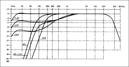
This is a six position rotary switch, allowing different filter possibilities to be switched in or out.
LFA 2 Low frequency attenuation, -8 dB at 50 Hz.
LFA 1 Low frequency attenuation, -4 dB at 50 Hz.
FLAT The machine has a linear response.
HP 1 High pass filter, -10 dB at 50 Hz.
HP1+LFA1 Combination of high pass and low frequency attenuation, -14 dB at 50 Hz
and -3 dB at 400 Hz.
HP2 High pass filter, -20 dB at 50 Hz.
5.3. INTERFERENCE
To obtain a good signal-to-noise ratio, it is not sufficient to place the microphone well, it is equally
important that no interference can be introduced into the system. An explanation showing how this
interference occurs will be given and also the means to eliminate it.
ELECTROSTATIC INDUCTION
The microphone and the cable, which connects it to the Nagra and the plugs, should all be well
shielded. If these conditions are respected, no electrostatic induction can occur.
However, certain parts of some microphones are grounded by a simple contact, which is not
protected against corrosion. Often the plug shielding is similar, and certain cables have only a
symbolic shielding.
In these cases any electrostatic field can induce interference voltages into the system, in particular if
the Nagra is not grounded but is connected to a camera, which is not interference suppressed and
the entire system is at a voltage above ground. Hence, the ground itself, as seen by a cable, is a
potential source of interference. In other words, interference is introduced at the slightest defect of
the shielding. The induced interference can be at an audio frequency or a high frequency, which
can be detected within the recorder.
ACTION TO BE TAKEN AGAINST ELECTROSTATIC INDUCTION
1. Good shielding. Above all, check the plugs.
2. Avoid the conditions where the Nagra is floating above ground with an interference
voltage. One possibility is to use a photoelectric coupler between the camera and the
Nagra. Obviously, no trouble can arise if quartz crystal synchronization is used.
3. If, for any reason, it is not possible to follow the advice given, it is possible to reduce
the interference level by:
a) Using shielded input transformers, which attenuate the passage of indirect interference.
b) Using symmetrical input (with the middle point grounded, which will
attenuate the passage of direct interference.
c) In the most hopeless cases (such as with a radio transmitter close by) add
external filters.
It should be noted that the microphone preamplifiers of the Nagra 4.2 are already fitted with filters,
but their action only begins at around 500 kHz, because they are, above all, designed to reduce
very high frequency interference for which the usual shielding is ineffective.
MODULOMETER
The modulometer measures the peak value of the signal, irrespective of the form or the level, the
modulometer takes into consideration the strongest positive or negative value. It is equipped with a
memory, so the signal can be very brief, but the memory ensures that the meter needle advances
and stays there for sufficient time for the operator to read it. The essential advantage of the
modulometer comes from the fact that the measurement it gives is that which concerns magnetic
recording, in other words it is the signal peak, which saturates the tape. The average value of the
signal (as much as it concerns the listener) is of no importance to the tape. In particular, while
recording noise, the modulometer indication is always exact, no matter how long the duration of the
noise.
The scale of a modulometer can be logarithmic, i.e. linear in decibels. In the case of the Nagra, it is
possible, for example, to have a range of 70 dB. This allows the exact appreciation of even the
lowest sound levels. Nevertheless, it is preferable to limit the range from -30 to +5 dB, to help
operators who are used to VU meters, which are not logarithmic.
The operator, on seeing the needle move, knows that his level is greater than -20 dB.
VU METER
In the days of electronic valves (tubes), a modulometer was very costly, and the rudimentary VU
meter was often preferred. Later, it was noticed that the VU meter still maintained a certain following
and because of habit and standards many radio stations still use them.
A VU meter is a simple rectifier voltmeter whose response time has been standardized. If the signal
to be measured is continuous, (e.g. a whistle) the VU meter will indicate a value the same as the
modulometer, but if the signal is intermittent (e.g. speech) the VU meter will only indicate an
average value, i.e. considerably lower than the instantaneous maximum levels.
For speech, it has been found that this average value is approximately 8 dB lower than the peak
value. By increasing the VU meter sensitivity by 8 dB, an indication of 0 VU. is obtained when the
peaks reach the maximum value. This works relatively well in practice. For noise, the indication of
the VU meter evidently becomes very inexact, and renders it practically useless.
The v.u. meter, however, has certain advantages:
a) Speech-music balance. If speech and music are recorded with a modulometer so that
the peaks of the signal do not exceed the maximum level, subjectively the music
appears stronger. This is due to the more continuous character of music signals.
Therefore, in a mixed program, it is necessary to modulate the speech more strongly
than the music. This can be done by modulating the music correctly and over
modulating the speech or by under modulating the music.
It is to be noted that a slight over modulation of speech is not catastrophic: a
transmitter is fitted with a limiter, as in the Nagra 4.2, which cuts peaks exceeding the
maximum level. The subjective deterioration of the sound quality remains
unnoticeable. On the other hand, a strong modulation increases the range of the
transmitter and is of direct interest for commercial radio stations.
A VU meter under indicates the speech. In modulating a program to 0 VU the speech
will be over modulated and the music under modulated. From this point of view, the
VU meter seems to be of more interest for mixed transmissions whose quality is not of
great importance, but whose range should be as large as possible.
On the other hand, for a transmission, which is wholly musical, the range of the
transmitter tends not to be used to its full advantage with a VU meter.
b) The VU meter has a scale, which is not logarithmic. For the needle to move, it is
necessary that the level exceed -20 dB. This causes the operator to compress greater
than is necessary, that is to increase the level of the pianissimo. This reduces the
quality of a musical transmission while increasing the range. On the other hand, it is
favorable if the listener is in a noisy ambience, such a car or a cinema hall.
CONCLUSIONS
The problem to be resolved is to know if the Nagra should be fitted with a modulometer or a VU
meter. The modulometer allows the use of the full dynamic range of the recorder whether for noise,
speech or music. The balance of the sound can, in any case, be achieved during the transfer.
If a mixed transmission of words and music should be recorded on the Nagra and transmitted as
recorded, the operator can simply modulate the speech to +2 dB or even +4 dB, and the limiter
takes charge of any peaks, and the music to 0 or even -2dB.
The VU meter is only justified for radio corporations where it is standardized because of operational
habit.
Biasing in Tape Recording
A music signal alone cannot be used to produce a faithful tape recording of a sound because the magnetization of the tape is so sensitive to its previous magnetic history, even the effects of the signal recorded just ahead of it. A high frequency bias signal is typically applied to the tape through the tape head along with the music signal to remove the effects of this magnetic history. This large bias signal (typically 40 to 150 kHz in frequency) keeps "stirring" the magnetization so that each signal to be recorded encounters the same magnetic starting conditions. The necessity for biasing has its origin in the magnetic property called hysteresis - the magnetic material tends to hold onto any magnetization it receives and must be actively driven back to zero to start over. Magnetic emulsions made with chromium dioxide require a larger biasing signal to make use of their wider dynamic range, so modern recorders have different bias settings for iron oxide, chromium dioxide, and metal tapes. With optimum biasing, the recorded magnetic image is proportional to the signal current applied to the record head.